

Spectrum Analyser
Last update: 24/06/2025
Hardware repo Firmware repo 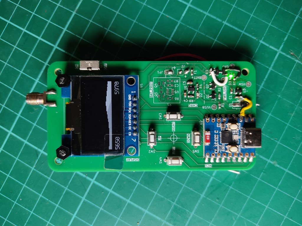
First Person View (FPV) drones are a testament to the power of miniaturisation of electronics in recent years, with a drone weighing a few 100g capable of exceeding 70mph and accelerating faster than an F1 car. The FPV drone hobby has a strong culture of tinkering, with many building their own drones from parts, especially historically, and this is a big reason why I became involved in the first place.
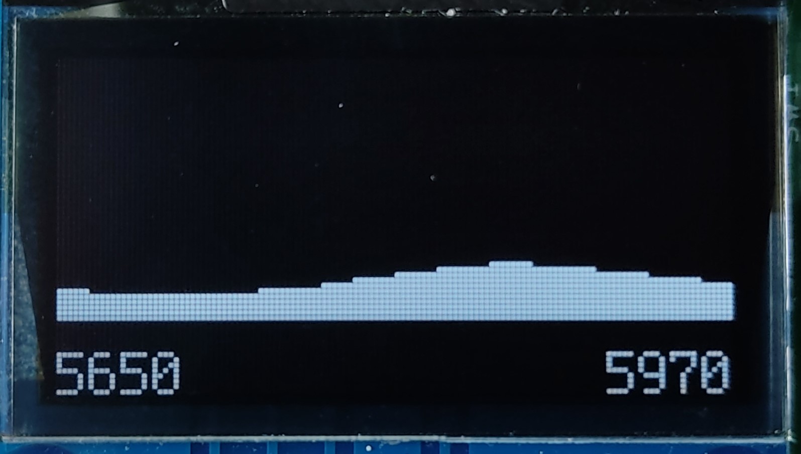
When flying drones in a group it is important to consider what frequency each is transmitting video at. Typically video is transmitted over the 5.8GHz range which is split up into around 8 non-overlapping video bands. Ideally drones will transmit at bands that are as far apart as possible and where there is minimal background interference. However, without a device capable of inspecting the activity in this frequency range, it is not obvious what these bands are.
To tackle this problem, I decided to create a hand-held device to inspect the 5.8GHz frequency range and report current signal strength. For the device to be useful, the following requirements were set:
- Graphical user interface
- Near real-time signal level display
- Multiple programs for different analyses
- Button-based input
- Battery powered with internal charge circuitry
Prototypes
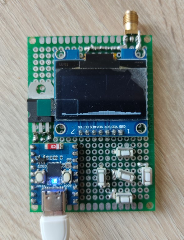
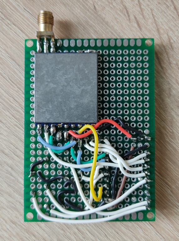
Before the final system was created, there were two prototypes to test ideas and functionality in isolation. The first prototype on a breadboard was used to figure out communication between the micro-controller and the receiver module and display. The second prototype demonstrated integration of the main system parts. It was constructed on a proto-board with the final MCU module, display and receiver with buttons for input.
Hardware
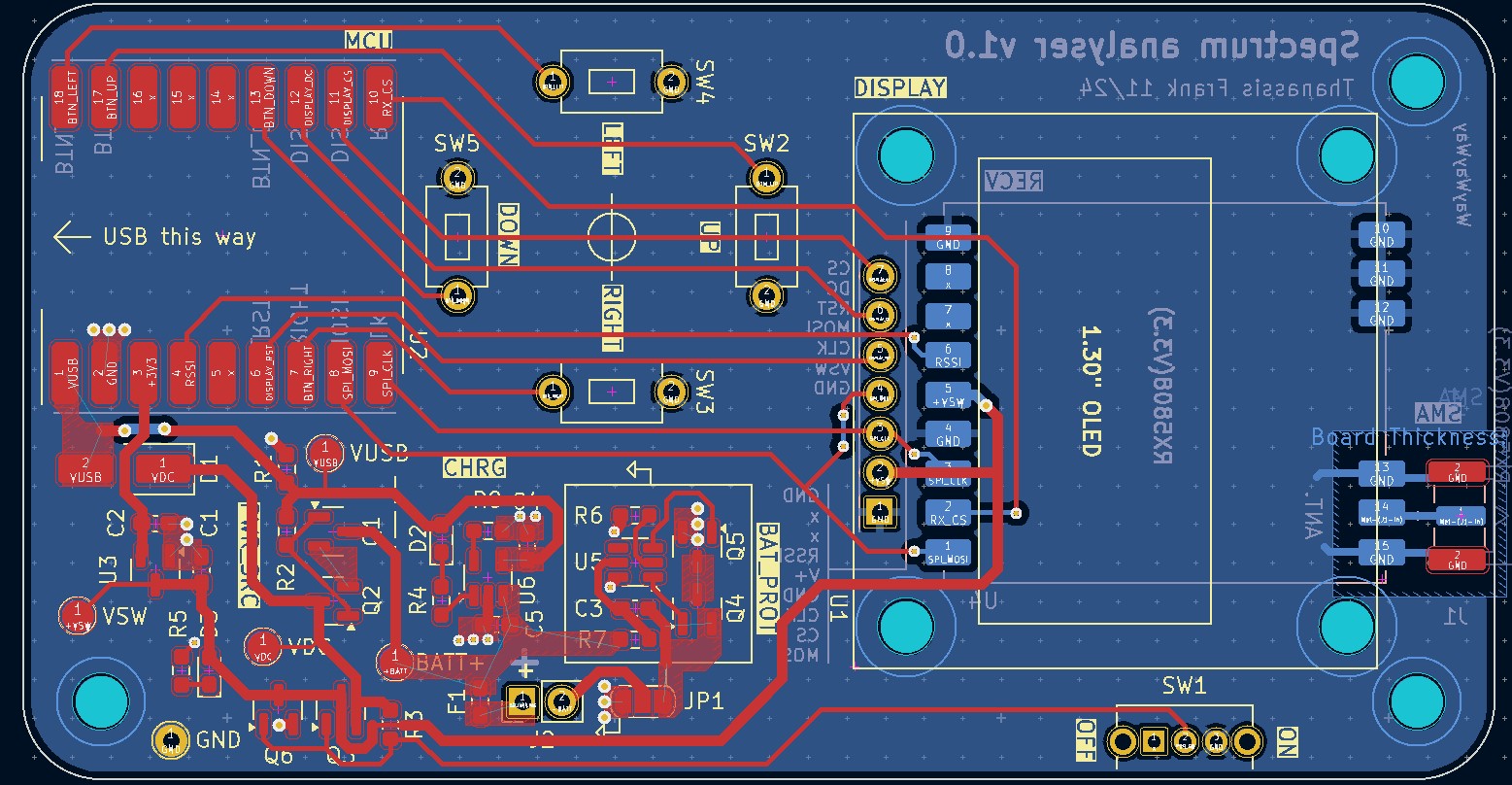
The board is 2 layers and was designed using KiCAD with simplicity in mind. The MCU is the ESP32-C3 which is used as a system-on-board that communicates with the receiver module and the OLED display module via a shared SPI bus.
The heart of this project is the widely available and inexpensive RX5808 radio module. Crucially, it outputs a real-time signal strength (RSSI) for the current centre frequency as an analog voltage which is read by the MCU.
Power is drawn from either an on-board LiPO when hand-held or the USB port of the MCU module when plugged in. The USB connection is also used to charge the on-board battery. In the name of simplicity, there is an option on the board to bypass the battery protection IC which sits between battery and the device GND.
Layout of the board began first with footprint placement, emphasising adjacency of related components to reduce trace length, minimise needed cross-overs and maintain compact board dimensions. Care was taken to place external interfacing components such as buttons, the USB port and mounting holes at round positions with respect to each other to simplify the design of any enclosure. The higher frequency traces like the SPI bus were routed first to ensure they had direct paths. The pin assignment of the MCU was also optimised.
During bring-up, the known-functional prototype firmware could be used with an altered pin assignment. Issues were discovered with the power supply with the main supply rail not fully turning off. This was diagnosed and fixed by adding a low-side transistor to the switch, creating a CMOS arrangement that actively pulls the supply up and down. The 3.3V LDO on the MCU module also interfered with that on the board and so was removed. The above image of the board layout includes these changes to the power supply circuitry.
In the next version of the hardware, the improved power supply will be included as well as improvements to the copper balance by adding ground pours on the front side of the board.
Firmware
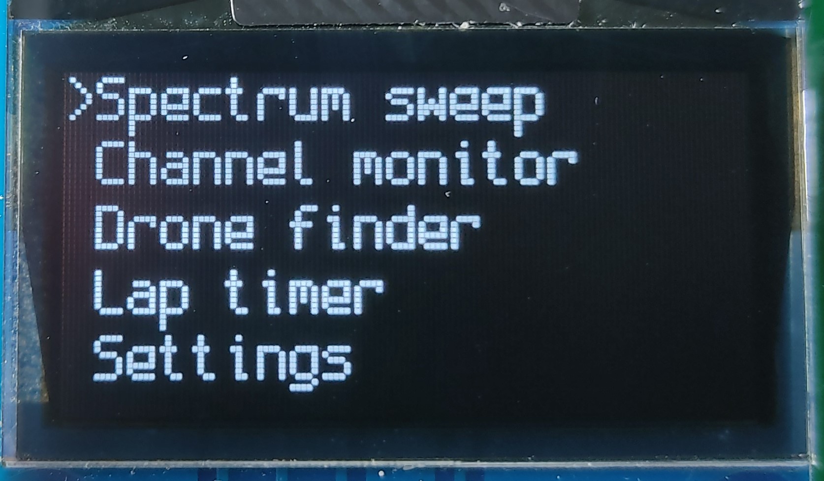
The firmware for this device is written in C using the ESP-IDF SDK which is built upon FreeRTOS. There are a few different interacting tasks controlling the receiver and user input with queues between tasks for communication. The GUI is written using the u8g2 library.
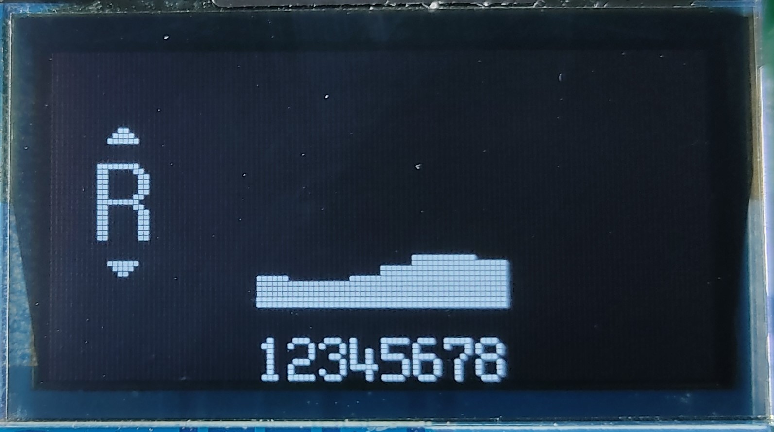
The main menu allows selection of one of the included programs which offer different analysis facilities to the user. Currently, a program showing the whole frequency range and one which samples the bands within a selected channel have been created.